Project #8
Breadboard Power Supply
PCB Design
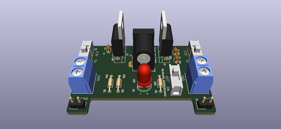
A breadboard power supply PCB that takes a barrel jack input and provides switch-selectable 5 V or 3.3 V output rails for both sides of a breadboard. The design uses an LM7805 for fixed 5 V and an LM317 adjustable regulator configured for 3.3 V. Dual header pins and voltage selection switches make it easy to integrate into prototyping setups.
Bill Of Materials
Ref Designator(s) | Component | Value | Notes |
|---|---|---|---|
U1 | Voltage Regulator | LM7805 | Linear regulator, fixed 5V |
U2 | Voltage Regulator | LM317 | Adjustable regulator, configured for 3.3V |
J7 | Barrel Jack | Power input connector | |
SW1 | Slide Switch | SW_Wuerth | Power board on or off |
S1, S2 | Slide Switch | EG1218 | Output voltage selector |
J1, J2 | Male Header | 2x3 | Breadboard rail connectors |
C1, C2 | Capacitor | 10µF, 0.1µF | LM7805 setup caps |
C3 | Capacitor | 1µF | LM317 setup caps |
J5, J6 | Screw Terminals | 01x02 | To mount on breadboard |
D1 | LED | 5.0mm | Power indicator LED |
R1 | Resistor | 330Ω | Current limiting for LED |
R2, R3 | Resistors | 330, 560Ω | Setup for LM317 |
Images

Board Schematics

Board Layout Image

3D Board Image
Board Schematics
Notes
I wanted a compact, breadboard-friendly power module that could supply both 5 V and 3.3 V rails simultaneously, with flexible switching so I could power different subcircuits without external regulators. Many breadboard power modules in kits are somewhat generic; designing my own helps me understand regulator tradeoffs, layout constraints, and conversion efficiency. The goal was also to integrate it cleanly; dual headers, compact footprint, clean traces.
I chose the LM7805 for its simplicity and stable 5 V output, and LM317 because it’s a classic adjustable regulator and lets me set 3.3 V using a resistor divider (per datasheet spec). I added input and output capacitors (as recommended in datasheets) to maintain stability and reduce noise. The switches allow me to select which voltage rail is active (e.g. turn off 3.3 V when I only need 5 V). The header pins are mirrored so both sides of the breadboard can be fed.
When laying out the PCB in KiCad, I prioritized short paths for the high-current traces (input to regulator, regulator output to headers). I kept ground planes or wide ground fills to reduce resistance and to help with thermal dissipation. I placed capacitors close to the regulator pins to reduce parasitic inductance. I made sure the board’s physical outline would match standard breadboard spacing so it fits snugly. Also I left some margin for mounting holes or mechanical stability.
Check out my other projects here!